Finally, the first step for Virtual Reality to meet the real world. In order to have interactivity with computers (have computers understand us) we must have three important things. Transducers, circuits and microcontrollers. Circuits are the the bridge to communication and I am exited to finally put together all these interesting parts that I always saw inside electronics but never knew what they did. Slowly it is all becoming more clear.

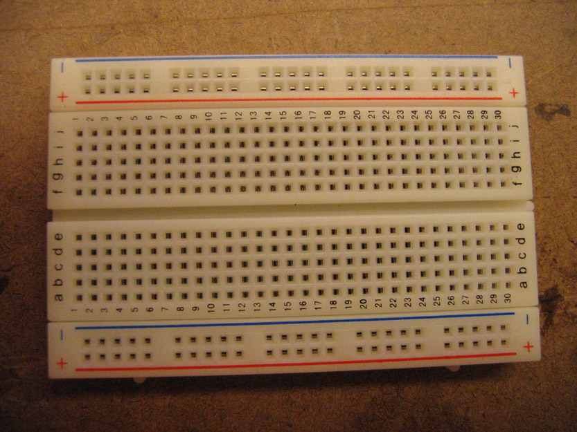
This is a Breadboard, it is used to make circuits. Its design enables to put together components with ease.

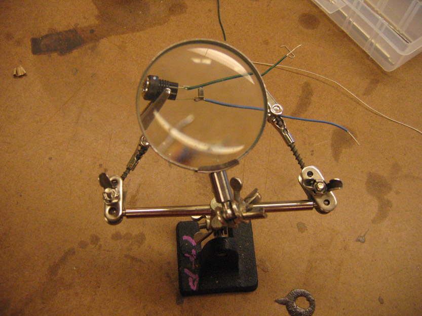
Most times, when you get parts from the shop they are not wired, so some soldering needs to be done to make sure the wires don’t get loose and loose the connection.

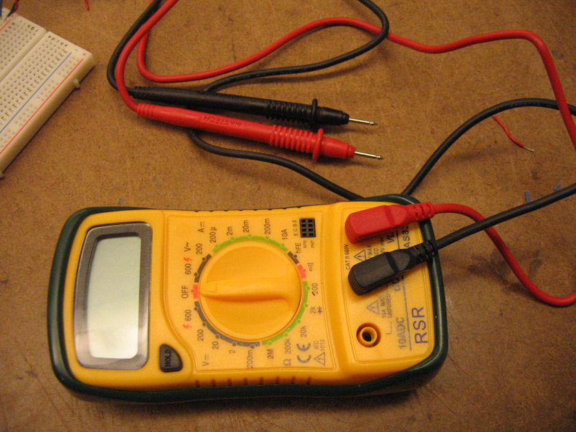
In order to test a power supply, see how much voltage something has, to check the resistance or to check the amperage of a current, a multimeter is needed.

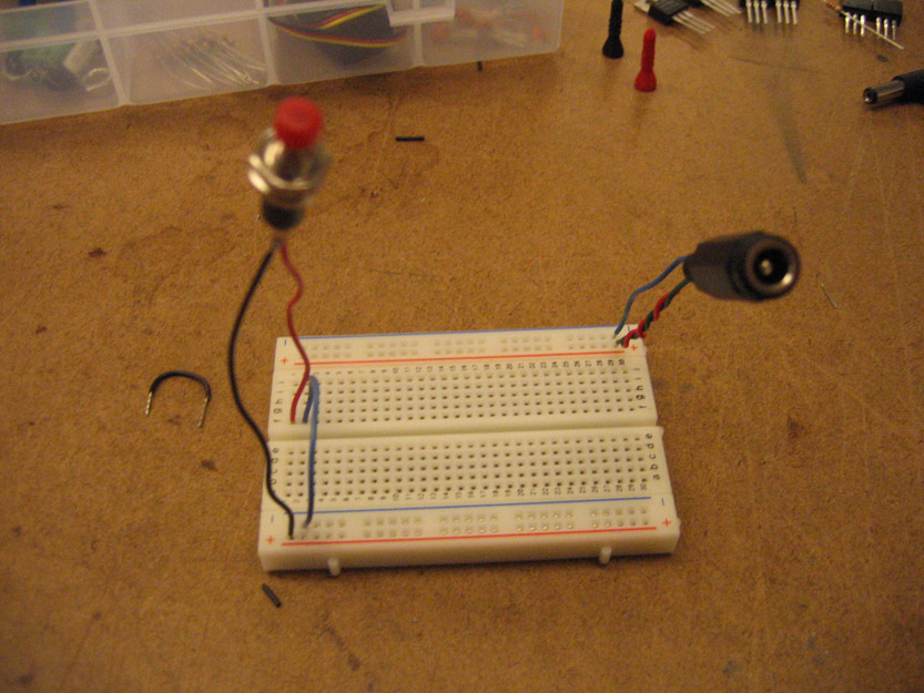
Once you have soldered components, you can start plugging them in to the breadboard. In this case I have a power switch and a power source input.

I then add a 5 volt transistor, some resistors, a potentiometer and some LEDs.

Once everything was in the breadboard, I turned on the switch and nothing burned out! (this time.)

Before I actually successfully had a working circuit, I had many LED casualties due to the fact that resistors come in different ohm capacity. The resistance of the resistor is indicated by the color bands on it. I am red and green colorblind so its really hard to tell what is green, red and brown. Before I learned that you can test the resistance with the multimeter, I was doing trial and error (with out success.)